And now, just when you thought it was safe comes. . .
Son of It Came From The Junkbox!
by Dan Petersen, W7OIL
(Advanced Builders Project)


Back in May, 2000 appeared in the hallowed pages of the Newsletter my first article, “It Came From the Junkbox”. This was a set in which I picked up DX for the first time – a true thrill indeed. Before that time I always thought that anyone who claimed to have heard DX on a crystal set had been hit by lightning once too often while stringing antennas. Now I am a believer as I have heard an amazing amount of stuff with the different sets I have built. For a while I have wanted to build a DX set that incorporates several of the tricks I have learned in my tinkerings. In this light, I designed a circuit that uses the best of the “Mystery” set, The “Like-A-Flash, Senior” and a new idea (for me at least), the use of a large air-wound tuning coil. Another feature I would find handy is some way to spread out the upper portion of the Broadcast Band. Last but not least I wanted to have a switchable detector where I could jump between a diode and a detector stand.
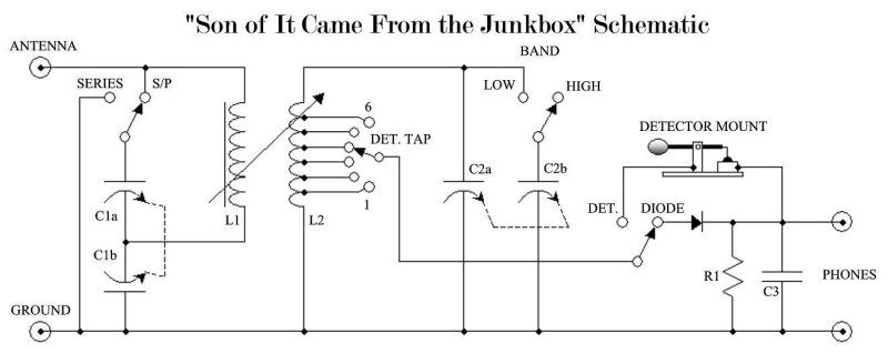
The construction of the “SoICFTJ” is going to require some explanations so bear with me. We might as well start at the antenna and work our way back. Referring to the schematic, we see that there is an antenna and ground connection that goes to the coil-capacitor circuit L1 – C1. C1 is a dual gang 365pF variable available from the Xtal Set Society. L1 consists of a 4” by 3/8” diameter ferrite rod that is available from Amidon Associates. Something else you can do is to go down to the local Salvation Army thrift store and buy a radio for 50 cents and pull the ferrite rod out of it. Take off windings until you have 50 turns left and there you go. For those of you who have the ferrite rod I first described, cover the core with paper or masking tape and wind 50 turns of #24 onto the core. I secured the ends of the coil with a bit of tape and then covered the whole shebang with heatshrink tubing.
Click on the schematic image for a larger view for printing.
PARTS LIST
C1 – 365pF dual-gang variable capacitor
C2 – Dual-gang variable capacitor: Section “C2a” = 90pF, “C2b” = 340pF Available from this website... (Click here) Part stock number (15-009)
C3 – .001uF to .002uF disc capacitor
D1 – Germanium diode (1N34 or equiv.)
L1 & L2 – See text
R1 – 15,000 ohm ¼ watt carbon resistor
S1, S3, S4 – DPST switches
S2 – 2 pole, 6 position rotary switch (Available from this website (Click here) , Part stock number 19-0013)
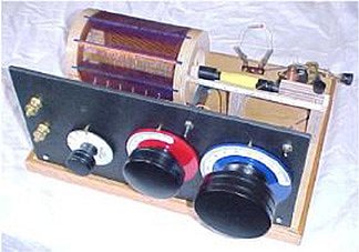
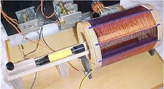
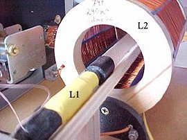
As seen in the included photos I have placed the coil L1 on a wooden “channel” in order to be able to move L1 into L2 in a “Loose coupler” configuration. I left the coil leads long enough to allow free movement. The coil L1 is used in conjunction with C1 and S1 to form a switchable antenna tuning assembly. When the switch S1 is in the “SERIES” position, L1 and C1 form a series circuit between the antenna and ground. Flip the switch to “S/P” and the antenna circuit is tuned with a series/parallel tuned circuit, similar to one of Mike Tuggle’s sets. My thanks to Mike Tuggle for his input. This type of tuning has been used in many circuits including my “Mystery Crystal Set”. Performance will vary with the type of antenna and ground system so there are no hard and fast rules in the operation of this circuit. Try both series and series/parallel modes while tuning. I find one way works well on one end of the band while the other mode works best at the other end.
Construction of L2:
I wanted to have a large, high-Q coil for the main tuning coil, referenced
as L2. I also wanted to have as little dielectric effect as possible so
I came up with a scheme for an air-core inductor. I took a piece of ¼”
Baltic birch plywood and cut four disks 3-1/2” in diameter with 2-1/4”
holes cut into the centers. I then cut out eight notches, each 1/8” wide
by ½” deep into two of the disks. I then glued one of the notched
disks onto each one of the un-notched disks. While those were drying I
prepared eight ½” by 5-1/8” strips out of lexan plastic. Once sanded
to shape I taped all eight together and cut small notches every 1/16” into
one side of the strips, just deep enough to hold the wire steady. When
the end plates were ready I assembled the whole thing by epoxying the lexan
strips into the notches and clamping the whole assembly to hold it in alignment
until it dried. Later I varnished the end plates and got ready to wind
the coil. The coil was wound by drilling a small hole in each end plate
near the outside edge and looped the wire through to anchor it. Then I
started to wind. Once I finished a turn I moved the wire over one notch
and continued winding. Once finished I looped the wire through the other
small hole and voila!, a nice, big air-wound coil. I used 74 turns of #20
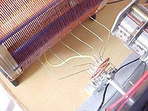
wire and it came out right on the money at 240uH. This being a tapped coil,
I scraped off the insulation every 10 turns and soldered a bare wire to
the coil. I then ran the tap wires to the switch S2. Please refer to the
detail photo to see what I did.
And Now . . .The Rest of the Story:
I used one of Mike Peebles dual-gang variable capacitors for the main
tuning control. These beauties have 340pF on one gang and 90pF on the other.
They also sport a plastic tuning shaft and a stout metal frame. I wired
the 340pF gang to a switch, S3, to enable me to switch this gang in or
out of the circuit. The 90pF section remains in the circuit all the time.
With the switch closed (“LO” position) the set tunes over the entire Broadcast
Band. Switching the 340pF section out of the circuit (“HI” position) spreads
the upper third of the BCB over the entire 180-degree swing of the tuning
cap. In a “regular” circuit you will find that the upper half of the band
is scrunched into the last 20% of the tuning range. The “bandswitching”
reduces this problem considerably.
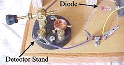
The remainder of the circuit is relatively straightforward. The detector select switch, S4, is connected to the common terminal of S2, the detector tap select switch. This switch allows me to select between a catwhisker detector and a germanium diode. You may note in the photo that the diode assembly consists of two alligator clips mounted to a terminal strip. I can easily change diodes for evaluation purposes with this gizmo. The eagle-eyed will also notice that there is no crystal in the detector mount and that it is not even connected to the rest of the circuit. This picture was taken when I had the detector mount temporarily disconnected. I like to have both detector systems in place on a DX set for there are times that a catwhisker detector works better than a germanium diode! Theory dictates that this is not possible but theory also says bumblebees can’t fly. Anyway, most of the DX chasers include a catwhisker detector in their arsenal of tricks. The ability to change diodes quickly also adds to the versatility. Capacitor C3 acts as an RF shunt while R1 guarantees a DC path to ground regardless of the type of phones you use.
Operation of the SoICFTJ:
Once I got the whole whiz-bang together it was time to try it out in
the real world. I connected it to my wind-damaged “RMS Titanic” antenna
and the ground rod. One end of the antenna is about 3 feet off the ground
and the other is still up about 30 feet. It sags badly and is spliced in
two places but I still get signals in. I’m gonna have to get up on my hind
legs and fix that bugger before winter sets in. I set the switch S1 to
“SERIES” and set the antenna-tuning cap C1 about half meshed. S3 was set
to “LO” and the detector switch was set to “DIODE”. Pop a set of cans on
my ears and let’s see if this thing hears. Tuning across the band I find
that the set has exceptional selectivity and good volume. I can easily
separate local stations at 750 and 860 KHz. You may have noticed in the
overall picture of the set the oversized knob on the tuning control. This
is for a finer “feel” when tuning. I am teetering on the edge of mounting
a vernier drive on the tuning control. A large knob is a good way to go
if you can’t get a hold of a vernier.
So the set works fine in the daylight. Let’s see how it dances in the dark. After nightfall I tried again. As it was still early evening in the summer I didn’t expect much. Much to my surprise I picked up KGO-San Francisco, KBOI-Boise, KFBK-Sacramento and numerous “peanut-whistles” in rural Oregon and Washington. I tried out the “HI” position on the band switch and found that the upper part of the band was nicely spread out. The “HI” band starts at about 1100 KHz and extends to 1750 KHz. I can hear the telltale murmuring of numerous stations in the background so I stay where I am and listen to see if any one of them rises out of the babble. One does a bit and it turns out to be Fresno, California. Not bad for a summer’s eve. As with all sets in the genre, this one has tuning interactions between the positions of the variable capacitors and the position of L1. You just have to work with a new set until you get used to its idiosyncrasies. Logging the positions of the various controls when you get a station tuned in helps a lot.
This set was a challenge to build but I consider it a job worth doing. The tuning coil was the star of the show in my estimation closely followed by the suggestion by Mike Tuggle to use a ferrite rod coil for L1 rather than an air-wound coil. I always like to have a tapped tuning coil as it gives the operator an added edge when the balance between selectivity and sensitivity has to be modified. It’s a winner in my estimation.
Dan Petersen – W7OIL
La Center, WA
True wit: Do not be afraid to try something new. Remember, amateurs built the Ark and professionals built the Titanic.